bracelet thomas sabo thomas sabo sale thomas sabo charm thomas sabo jewellery thomas sabo outlet vibram five fingers outlet vibram five fingers sale vibram five fingers vibram chaussure vibram france


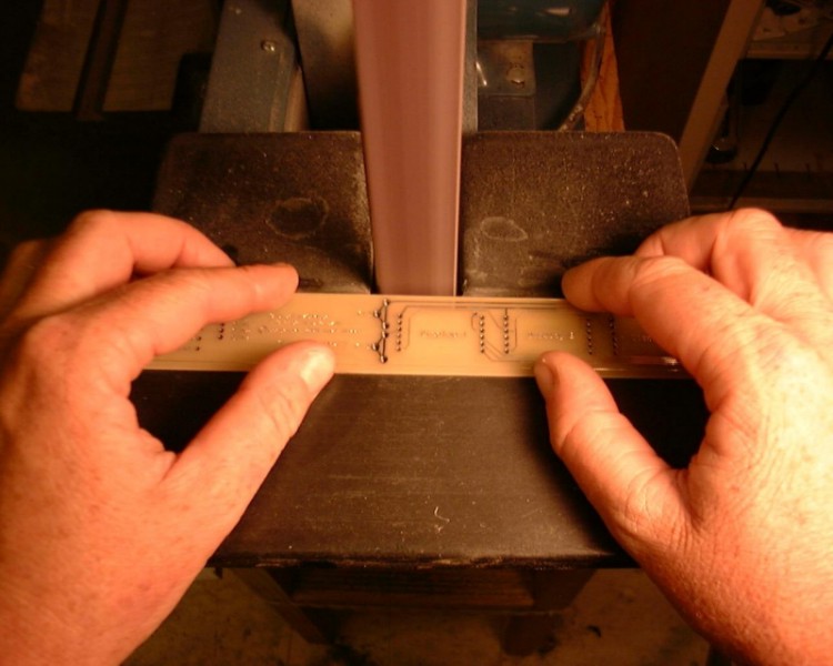
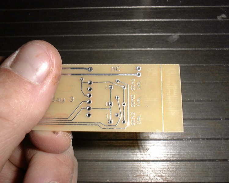
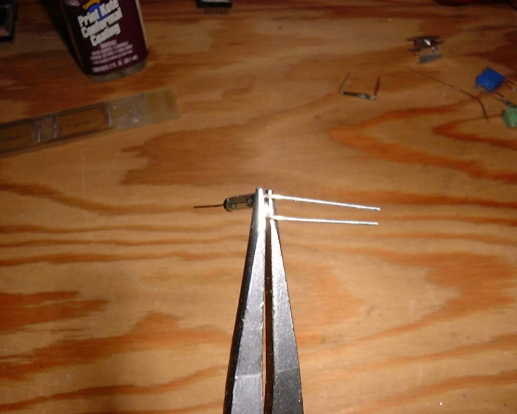
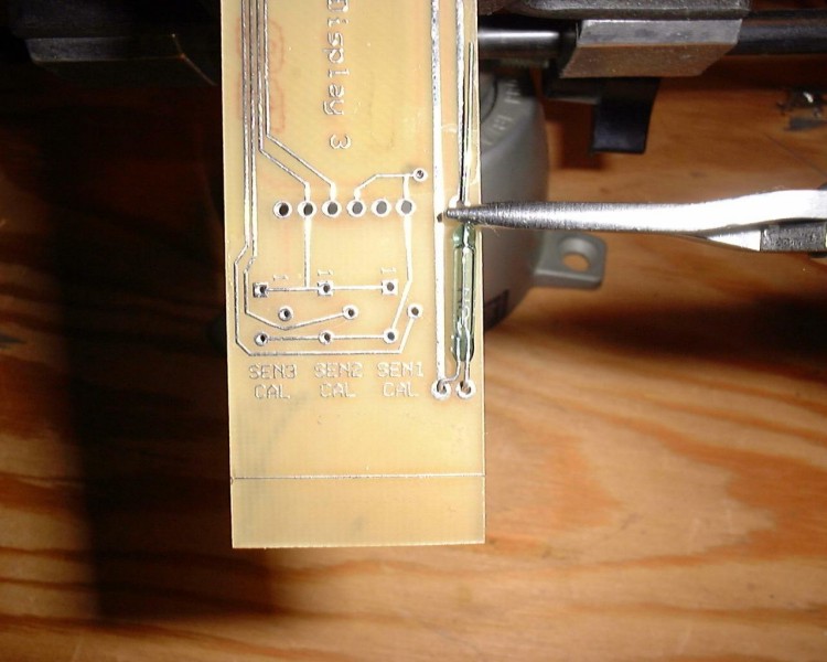
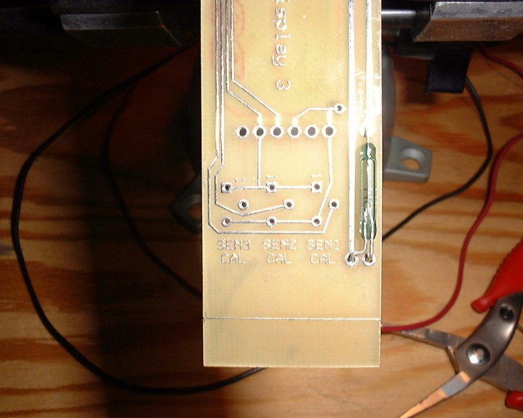
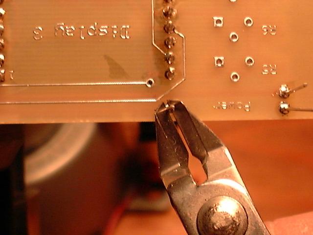
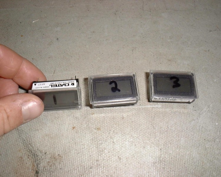
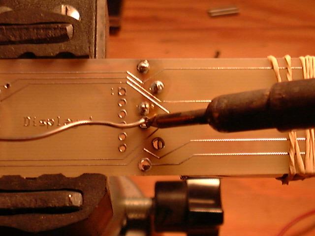
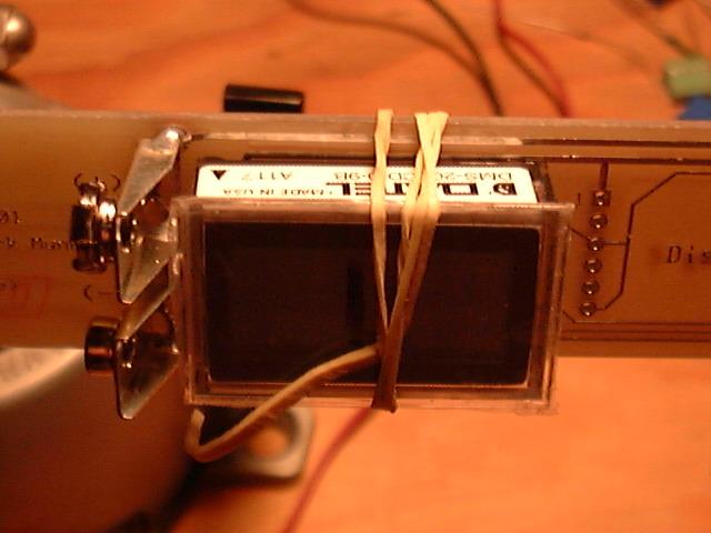
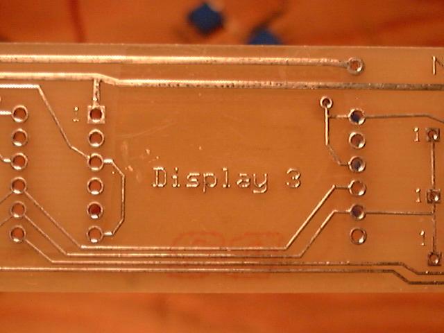
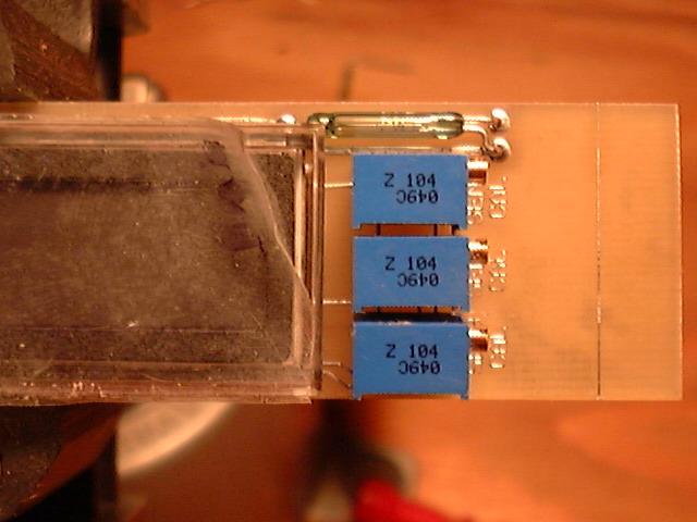
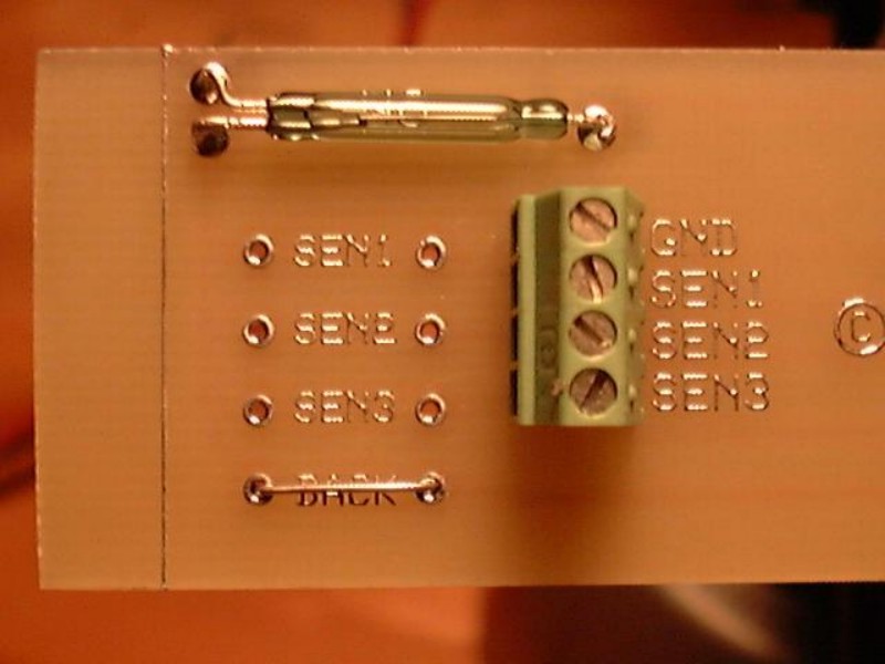
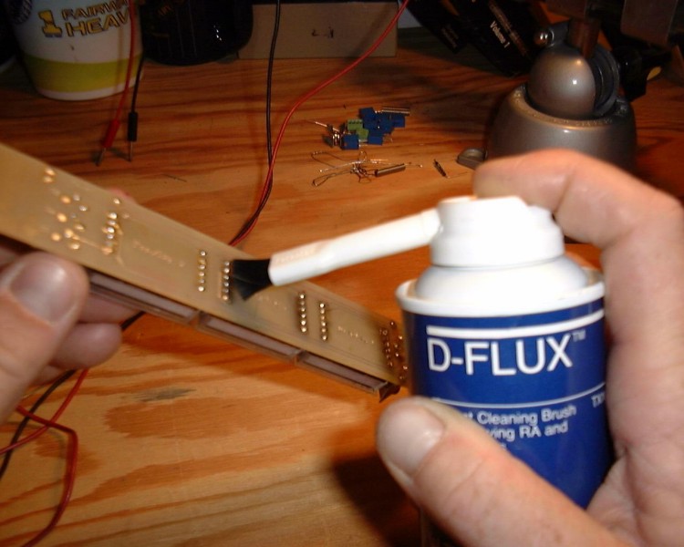
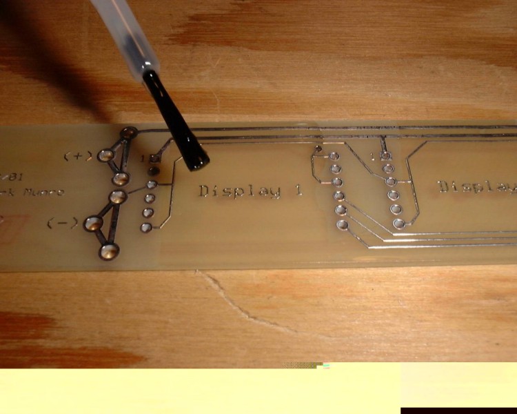
Assembling a 3 display board

Here's a brief run down of what it takes to put a board together


Const-01.JPG (118151 bytes)

The first thing you need to do is finish the board properly since the board comes just roughly cut out.  Here I'm using a 1" belt sander to sand into the outline trace of the board.

Const-06.JPG (101711 bytes)

If your real finicky you can file the last few thousandths into the trace.  

Const-08.JPG (65414 bytes)

Here you can see, sort of, that I've filed about half way into the trace and the trace is visible on the forward leading edge. 

Const-11.JPG (93087 bytes)

I'm now ready to remove the outline trace.

Const-03.JPG (60539 bytes)

The trace will pull off quite easily to remove it.

Const-05.JPG (84124 bytes)

ditto

Const-13.JPG (97112 bytes)

The tools required to do the rest of the job.

Const-28.JPG (68677 bytes)

Let's do the delicate part first...

I've used the needle nose pliers to protect the glass shell of the magnetic reed switch as I make the first 90 degree bend.

Const-29.JPG (78272 bytes)

The reed switch is then placed in the board and the needle nose pliers are used to hold and mark where the second 90 degree bend is made.

Const-30.JPG (79402 bytes)

Here I've fully installed and soldered in the reed switch for the power.

Remember to check to make sure you bend them the right way. Without a magnet present the power switch should have continuity between the two pins that have the traces running to them, and no continuity for the back light reed switch. 

Const-39.JPG (32460 bytes)

Flip it over and trim off the extra part of the leads with right angle cutters.

Do the same for the back light reed switch if you choose to use one.

Const-14.JPG (117538 bytes)

On the protective plastic sheeting cover mark the displays with numbers which you'll remove when your done.

Const-15.JPG (99936 bytes)

Turn all the pots fully clockwise.

Const-17.JPG (114648 bytes)

Hook up + 9 Volts to pin 1 and ground to pin 3.  Attach a DVM across pins 8(+) and 10(-).  Pin 1 is denoted by the black triangle on the white label and the pins are numbered consecutively around the display counter clockwise, while looking at the back.  So, in this picture pin 1 is in the upper right, pin 6 lower right, pin 7 lower left, and pin 12 upper left.

Const-16.JPG (95726 bytes)

Read the millivolts across pins 8 and 10 and record the value.

Const-18.JPG (78487 bytes)

Now do the same for the other two displays.  After you've got all the values, go back and using the trim pot on the back adjust the value across pins 8 and 10 to read the lowest value you recorded.

Const-19.JPG (62707 bytes)

Mix up some two part epoxy

Const-20.JPG (91861 bytes)

Cover up the trim pot to seal and lock it making sure the blob isn't to high that the display wont sit properly when installed on the board.

Const-21.JPG (38781 bytes)

Ready to roll.

Const-31.JPG (105240 bytes)

Put the battery clips on the battery and install it on the board, double check the polarity.  I find it useful to use a rubber band to hold it in place.

Const-36.JPG (34992 bytes)

Solder the battery clips in.  The polarity is correct .... right?

Const-37.JPG (33066 bytes)

Install the displays, lining up pin 1 on the display with .......

Const-38.JPG (33271 bytes)

..............Pin 1 on the board.  Pin 1 on the board is the square through hole and is also marked with a 1. 

Const-40.JPG (30993 bytes)

After you solder the displays in, trim the excess leads with right angle cutters, you can do the excess battery clip lead material while your at it.

Const-41.JPG (33999 bytes)

Next install the sensor trim pots.

Const-43.JPG (65671 bytes)

Install the header connector, backlight jumper or resistor, and the sensor load resistors if needed.  Again trim all the excess lead material from the back.

Const-47.JPG (84074 bytes)

D-Flux the back of the board to remove all the solder flux, double check all your connections and solder joints


    Const-44.JPG (94957 bytes)

So now we're ready to install the battery, test the power and back light switch, make sure there's no stray voltage between the sensor ground and the sensor positive connections on the header connector and then hook up some sensors.

Const-23.JPG (58857 bytes)

I didn't include this in the above description but I have started to use conformal coating on the boards I've put together.  It could aid the board and sensors if you should flood your housing.

Special Note 02/2005:  All boards now come with Solder mask, which is the green coating you see on standard industry PCB's.  So if you want to use conformal coating it only has to go over the the solder connections, not over the whole trace runs.

As of late I haven't been using it and assume I wont flood.

Const-26.JPG (77377 bytes)

Use it as you put the board together making sure that everything that runs a signal is coated when your done with the construction.  I usually start construction by coating the parts of the board I wont be able to reach after something is installed, with out getting it into the through holes.  The displays are the trickiest part.

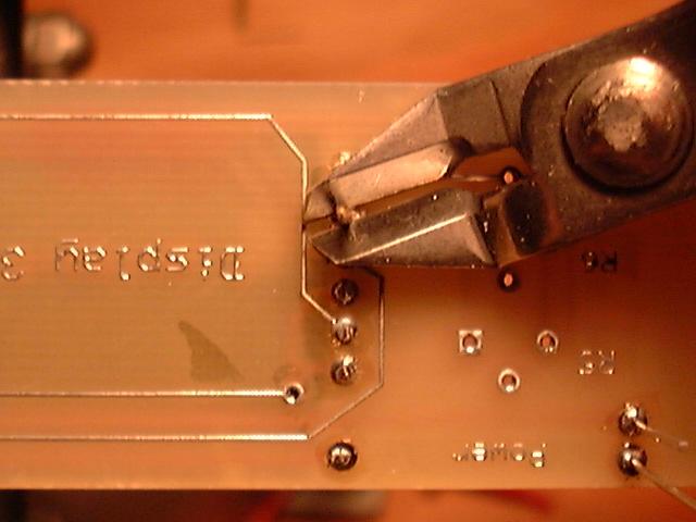
Well there ya have it.

HOME        Back to the display page