Sensors:
I
currently use the Teledyne K1-d
in my BP60. Since there isn't a lot of room between the
stainless cover and the top of the scrubber I chose the K1-d for
it's size.
3/10/2001- I was playing
around with my new R22D's and found that they do fit under the SS
centersection cover on the BP60, there wasn't a lot of room but they
did fit. I could press in on the top and feel it deflect
in a tad and hit the sensor. Some tests of your own are
warranted. I may in the future try to install one on in my O2
rig for testing and get away from the K1D's since the R22D's should
last much longer.
Loop flow direction (part 1):
All this talk about OTS CL's (over the
shoulder counterlungs) and Back mounted CL's
brings up a question I had regarding the loop flow direction in the back
mounted CL designs. Typically I understand the conventional loop flow to
be Diver=>Scrubber=>CL=>Diver. And one of the reasons I hear
for this is that your exhaled gas is warm and by going directly to the
scrubber it helps to keep the bed temperature up. Also it is easier to
exhale and push the gas through the scrubber than it would be to pull it
across the scrubber if the loop direction was reversed because we can
exhale stronger than inhale. Well I'm wondering what's wrong with having
the loop flow Diver=>CL=>Scrubber=>Diver ?
(1) Kevin mentioned
the other day, during the hypercapnia discussion, about having to push
the water through the scrubber bed to get the water out that was
introduced into the loop from the DSV. Well this wouldn't be a problem
in this Diver=>CL=>Scrubber=>Diver direction because the CL would act as a water
trap.
(2) All the gas, at least on my BP60, is injected into the CL. So
in the Diver=>CL=>Scrubber=>Diver loop flow direction the gas has some time to
homogenize before it gets to the diver. Where as if flow was conventional
Scrubber=>CL we inject gas and immediately breath the gas we just
injected which might have a high concentration of O2 (a concern when diving as a
mixed gas rig).
(3) I'm not sure
where the sensors are placed for other units but the best place I could
find for mine are directly on top of the scrubber. This allows the
sensors to get heated up by the scrubber and stay at an elevated
temperature. But, if loop flow is conventional Scrubber=>CL the gas
coming out of the scrubber and across the sensors is going to be at a
higher temperature albeit maybe not much. So condensation is more likely
to form than if the loop flow was CL=>Scrubber. The exhaled gas is
cooled a little in the CL and passes across the sensors which are warmed
by the scrubber and are more likely to be at a higher temperature than
the gas.
(4) With sensor placement on top of the scrubber if loop flow
is conventional Scrubber=>CL the gas the sensors are reading is
exhaled gas not breathed gas. With CL=>Scrubber loop flow the sensors
are reading the gas your gonna be breathing.
Loop flow direction (part 2):
I've been running my O2 unit by exhaling into
the CL and inhaling from under the scrubber. My thought here is that:
1)
If I exhale into the CL and am ascending, the gas that is vented off
hasn't gone through the scrubber and removed CO2 that didn't need to be
removed.
2) A lot of the water vapor that would be condensed out will be
condensing in the CL and not in an area where it has a higher
probability of getting into the scrubber material. Like if loop flow was
from the scrubber to the CL then as gas comes out of the scrubber it
will condense quickly on the SS cover. I'll also counter my own thought
by saying that the condensation would most likely roll into the CL from
the vents around the scrubber.
3) The Porex filter is on the bottom of
the scrubber canister and with loop flow from the CL to the scrubber the
Porex filter is filtering the gas before it goes into your lungs. This
helps reduce the Sofnolime dust ya get. I don't see that foam filter on
the top of the scrubber doing much filtering if the loop flow is from
the scrubber to the CL.
4) The gas is warmer and has more water in it
when it gets to you if the loop flow is from CL to Scrubber.
5) I
planned on attaching my sensors to the top of the scrubber canister with
some type of a fixture. As the canister and metal top heats up the
sensors also heat up. With loop flow from CL to scrubber the sensors
will be at a higher temperature than the gas flowing across them plus the
gas will be less saturated with water and condensation on the sensors
will be averted. I don't like the idea of mounting the sensors on a
surface that is not as warm as it could be. but I haven't yet played
with this so what do I know, just thoughts.
6) If I add gas/O2 into the
CL and have loop flow from CL to scrubber by the time the gas gets to me
it has been homogenized If loop flow was the other way, from scrubber to
CL, I'd be getting a quick O2 spike.
7) I agree that by breathing into
the bottom of the scrubber first the higher gas temperature will help to
get the scrubber going, but with a good pre-breath and the fact that
after you get it started the scrubber is surrounded with gas and not in
contact with the surrounding water, I don't think it adds much value
considering the other things.
Loop flow direction (part 3):
My logic, or illogic, was that we're trying to make
the loop as efficient as possible. I agree that venting gas that hasn't
been scrubbed yet will not produce a big savings, but all the little
savings add up. As John stated "The scrubbers on these rigs have a
'not so good' reputation for breakthrough", so why not optimize? My
point was that all the small savings add up. This isn't to say I'm not
going to try the loop direction the other way, I will. How about this as
another reason for CL=>Scrubber=>Diver loop flow. When your
purging the loop at depth with diluent to verify PPO2 meter readings or
purging with O2 on the hang gas is injected into the CL. If you use the
CL=>Scrubber=>Diver loop flow you inhale the gas you want to get
rid of and purge it through your nose. Do two of these then breath a
little bit, purge again. If loop flow was scrubber=>CL=>Diver the
gas you breath in from the CL, where the gas was just injected , is the
gas you want and now your going to purge it from the loop. Anyone else
have a different purge method that gets around this? Of course with the
CL=>Scrubber=>Diver loop flow and a purge your now purging off
scrubbed gas so I guess savings is not as much of an issue as efficient
purging. As Patrick said "the unit is not designed to work that
way", but I would also have to add that it wasn't designed to work
underwater either (3/2005 - Not exactly true). We're trying to make the best of a system that was
designed to keep people alive while fighting fires not to keep someone
alive at 130 feet.
Yes I have a foam pad on top of the scrubber but I
ass-u-med that it was mostly used to retain the scrubber material. I
can't see the foam absorbing moisture from the loop since its probably
at the same temperature as the gas going through it in the
scrubber=>CL=>Diver direction and at a higher temperature of the
gas in a CL=>Scrubber=>Diver direction. I find most of my
condensation/moisture in the CL.
Cleaning Porex filter:
I soaked my Porex filter in water for awhile and
then blew it out with air.
Trimming mold part line:
I was looking at my center
section last night as I was installing the wiring for my sensors and
noticed something. The "vent" area where the gas moves between
the CL and the scrubber on my unit had an excess amount of material left
over on the mold separation line which is inside these passages. I used
a razor knife to trim away this excess material and it looks to have opened up
these passages considerably. Seems like trimming this up will possibly
help to decrease the WOB.
Center Section Ports:
Yup, I used an
O-ring to seal them. I just bought a 5/16-24 stainless hex bolt and cut
a shoulder into it on the lathe added an O-ring and I was done. The
pressure gradient there is zero so no big deal. Bummer on the old unit
not having the material needed to put in new ports. I always wondered
why I had seen photos of BP60's with the center section rotated and the
plumbing attached to the old ports. I just figured it was easier for who
ever did the work.
Okay, now some new stuff, 3/2005.
Useless parts:
The stock parts I removed were the two tank
pressure gauge's, the End of Service Alarm (low tank pressure warning
whistle), the flow restrictor (O2 bleed "orifice"), one
section of the Over Pressure Valve (OPV), the compression spring that
pushes on the counterlung, cooling rings in the lid, the six plugs in the
backplate with the screen mesh, the harness, and the Anti-Anoxia valve.
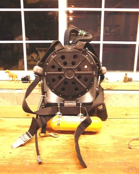
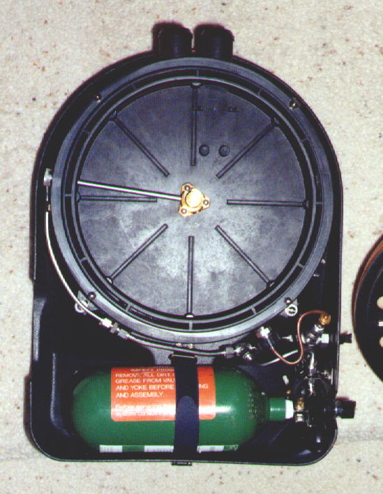
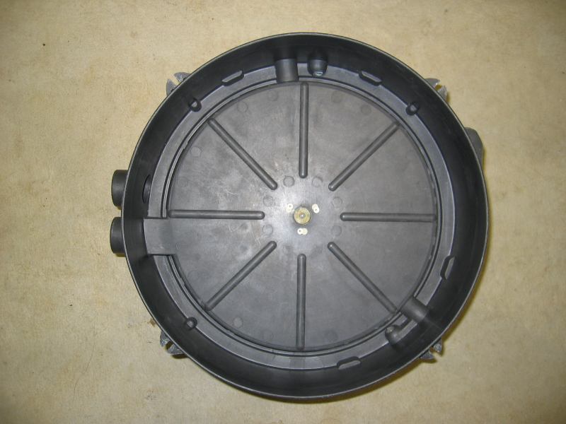
Backplate:
Note in this picture of my backplate
that I've added
about ten holes to the backplate to allow the water to move in and out
more easily. With the standard
six holes air flows in and out just fine but drop the rig in water
and the higher viscosity of the water makes for hard breathing.
The holes I added were slightly larger then the originals and the total
area of the holes equaled what's on the MK15 series Biomarine
rebreathers.
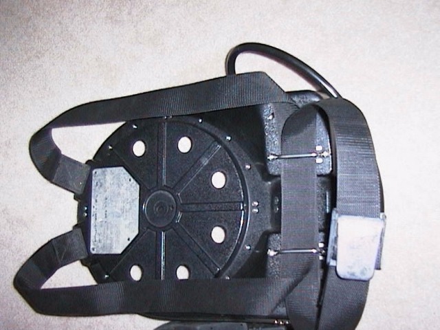
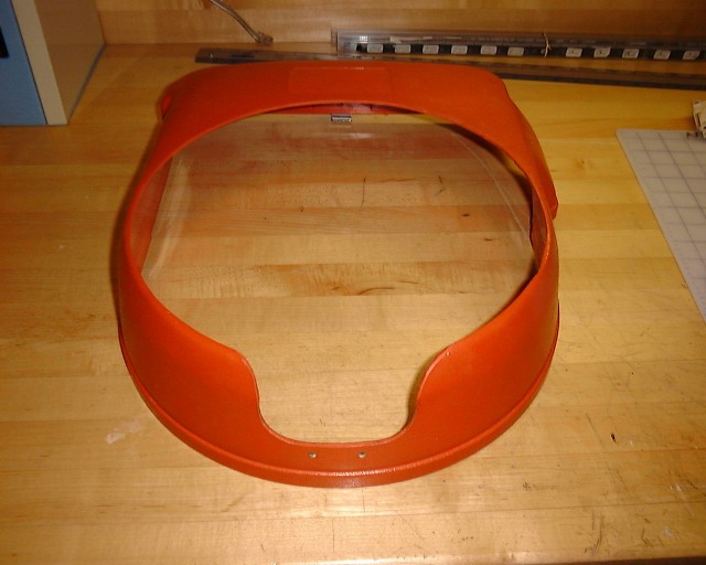
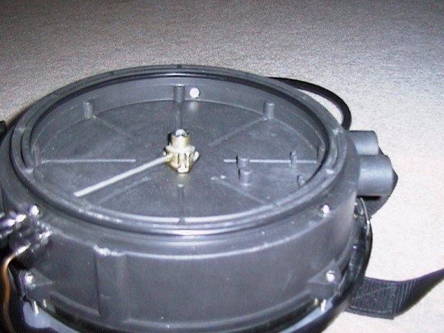
In this picture
you can see I made a ring to allow me to rotate the centersection so the
breathing hose connections were at the top of the rig and to increase
the counterlung volume a bit. I found the CL volume to be slightly
smaller then I liked and this fixed that problem. On the bench I
sucked all the gas out of the loop until the CL bottomed out, then with
the loop closed I took the biggest breath I could, I then opened the
loop and breathed out into the loop as much as I could. I made the CL volume so
it would just start to vent at the very end of my exhale. The ring
worked good but I'd make sure I radiused the inside top edge otherwise
it has a tendency to adversely affect the counterlung material. A
to scale AutoCad drawing of the ring can be found here
or a PDF file here.
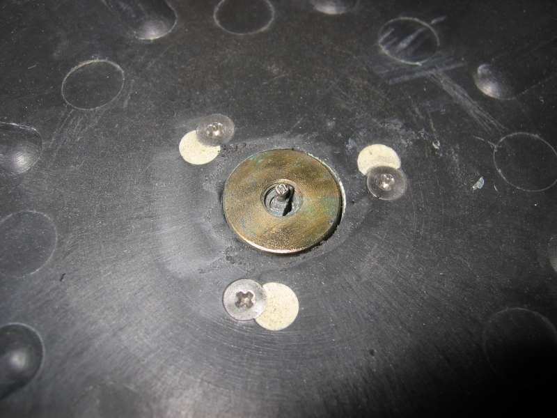
I've also used standoffs to raise the
centersection, not shown well here
(standoff in the middle right of the picture). This also worked
well. If you used standoffs on the original backplate you wouldn't
really have to drill the extra holes in the backplate.
Cover:
Two modifications I made to the cover
were to cut out a slot for the hoses to come out, now that they were at
the top of the rig. I also had to open up the center of the cover
where the scrubber lid comes through. After raising the
centersection a bit off the backplate, as mentioned above, it made for a
tight fit. A little plastic removal and things worked well.
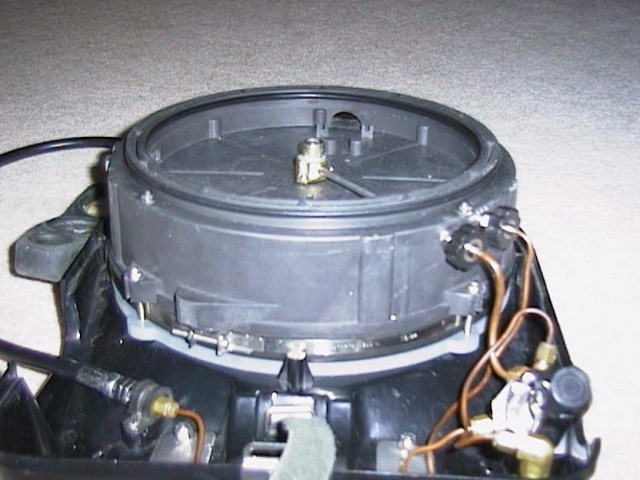
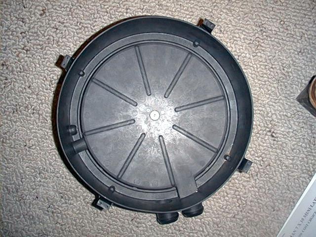
Centersection:
You can see in this picture
that I've rotated the centersection 135 degrees clockwise so the
breathing hoses are coming out of the top of the rig and that the gas
connections are still in the same orientation as the original. One of the things you
have to look out for in a BP60 is the extra material some molds have in
them to allow you to do this and others that don't. Here's how to check it out: disconnect the centersection
from the backplate, remove the CL, now while looking at the back of the
centersection check the area inside 135 degrees clockwise from where the
current gas connection fittings are. There may or may not be some extra
meat in the mold here to drill new gas connections holes. If you
have the extra material you can add new gas connections but if you don't
have the extra material all is not lost. You could always make a
banjo fitting like here,
Look here
to see a BP60 used with a banjo fitting, from www.divenet.com
Look here
to see a shot of a BP60 without the extra material.
Look here
to see a shot of a BP60 with the extra material.
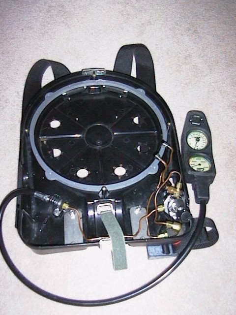
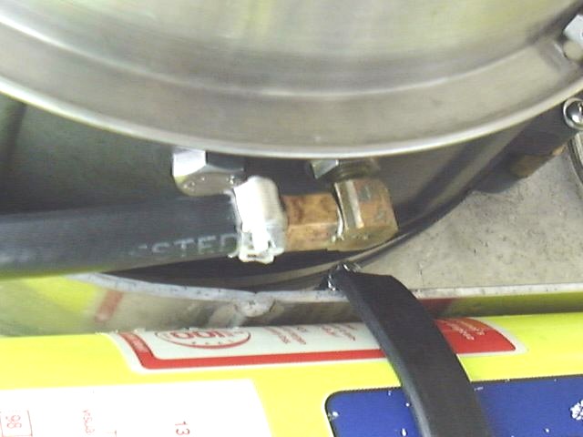
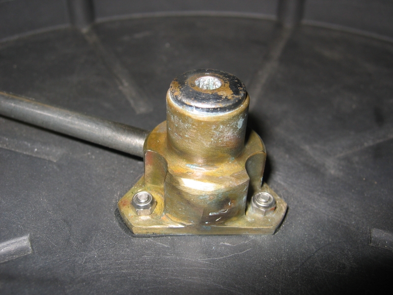
If you rotate the centersection, block off the old ports,
and drill some new ports, what else is there to do. Well here
you can see I've done that and can see the stainless tube that feeds the
shrader valve is installed in the new port. Unfortunately when you
rotate the shrader valve assembly the old holes don't line up with the
new position so you have to plug the old holes and drill new
holes.
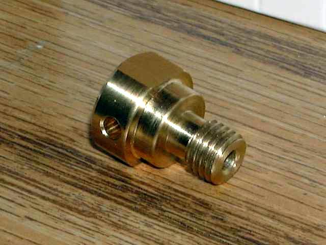
While we're on the shrader
valve assembly there were a few things that I needed to do to it to
make it work for me. I plugged the connection where the Anti-Anoxia
valve was connected and I removed the flow restrictor (O2 bleed "orifice").
To plug the Anti-Anoxia valve connection I inserted a machine screw and then silver soldered it
in place. I installed a standard first stage port plug where the
flow restrictor was. Check the shrader
valve assembly out here.
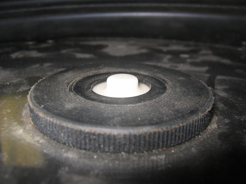
Over pressure valve (OPV):
The stock OPV has a dual stage vent and I thought
it just added extra height and lessened the effective CL volume. I
removed the top section of the OPV and removed the threaded portion of
the lower section on a
lathe.
Mouthpiece/DSV (Dive surface valve):
Currently I use a mouthpiece with DSV and hoses
from a Draeger Ray. The hose ends fit right onto the connections
on the centersection and although the hoses are a tad shorter then I
would like it works quite well. You can see the progression on my
homebuilt mouthpiece/DSV here. After
switching to the Ray parts I went back to the homebuilt one for a
comparison, there is none. The WOB on the homebuilt one is very noticeable
compared to the Ray's.
Just thinking, it might be an option to use the
original short sections of breathing hose with the screw on connections
on them and the Ray hose.
Copper tubing:
First Stage:
Scrubber:
Harness:
Tank pressure gauge on tank valve:
I'll be working on this ........ 3/27/2005