******* WARNING*******
This product is not intended for
uneducated users. It is provided for
experienced rebreather and mixed gas users ONLY. If you have not been properly trained by an internationally recognized technical certification agency and/or
don't have a firm grasp of electronics then DO NOT USE THIS STUFF. God forbid
you actually use it underwater, everyone knows water and electronics don’t mix.
This design, if used as part of a life
support system, could indirectly kill you, and it probably has faults. The designer does not warrant that it won't
get you killed, or that it will produce safe, reliable, results. This dive product is experimental, and if
you choose to use it than you do so at
your own risk. Diving in general is fraught
with risk and playing with things you don’t take the time to understand and
verify adds significantly more risk.
Introduction
In putting together an O2
rebreather and a mixed gas rebreather I’ve developed a few O2 display boards using Datel Digital Panel
Meters (DPM). The features incorporated
into the displays are, small board layout for fitting into a 1-1/4” ID clear
tube or other housings, epoxy encapsulated DPM, back lit DPM, calibration pots are easily accessible, DPM
has a low battery alarm annunciator and low power consumption , there is a
space for a sensor load resistor if required, and they can be used with O2
sensors outputting < 22mV in air.
Design
basis
The principle of operation for all the
display units are the same. The output
voltage from a galvanic oxygen sensor is feed across a load resistor, if
required, and to the input of a DPM.
The displayed value is adjusted to read correctly in a calibration gas
and pressure with an external gain adjustment.
A Teledyne K-1d oxygen sensor outputs ~10.5 mV in air and ~50.0 mV in
100% O2 at 1 ATA so by applying a displayed gain of two we have a
display that reads 210 and 1000 respectively.
Using the display units setup for use in rebreathers this would read 0.210 and 1.000 to represent partial pressure of O2 . On the display unit designed for use in
rebreathers or as a mix analyzer the decimal point is moveable to represent
Fraction of O2 or partial
pressure of O2 .
Typically an O2 sensor is
linear, meaning if you get 10.5 mV in air at 1 ATA (0 fsw) and 50 mV in air at
4.78 ATA (125 fsw) you should get 80 mV in air at 7.66 ATA (220 fsw). Which would read on our DPM (with a display
gain of two and the decimal point in the PO2 position) as 0.210,
1.000, and 1.600 PO2 respectively. O2
sensors read Partial Pressure of Oxygen and if you don’t know what that is I’d
suggest you start by reading Rich
Pyle’s “Diving Physics and ‘Fizzyology’”
http://www.bishop.hawaii.org/bishop/treks/palautz97/phys.html#Partial
Pressures .
DPM - The DPM I use is the Datel DMS-20LCD-0-9B, it’s a 0-200mV
input, 9-14VDC, back lit display, Figure 1.
This meter has an internal precision reference voltage which is feed
across an internal voltage dropping resistor and a potentiometer to pin 10
(analog common) with the pot wiper output on pin 8 (reference voltage). Typically the reference voltage out (pin
8) would be feed directly back into the
unit at pin 7 (reference voltage in).
You would then use the pot adjustment on the back of the DPM to
calibrate the display. I’m not going to get into how this DPM works except to
say that if you want a displayed gain of 1 so that a 199.9mV input voltage
would read 1999 on the display you need
100mV at pin 7 (reference voltage in).
But if you want a displayed gain of
two ,like we do for an O2 sensor, then you would put ~50mV on
pin 7 (reference voltage in). So in
order to achieve an adequate display gain and take advantage of the internal
precision reference voltage a 25 turn 100k ohm pot is placed across pin
10(analog common) and pin 8(reference out) with the pot wiper connected to pin
7 (reference in), Figure 2.
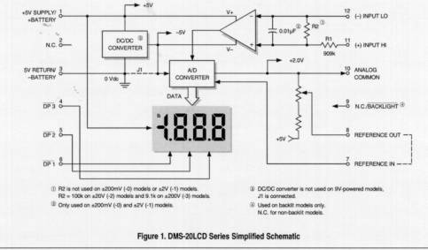
FIGURE 2